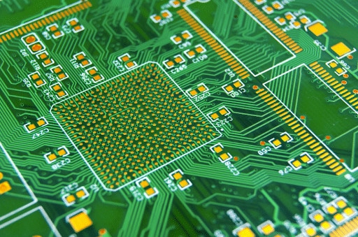
Do you know what’s the secret behind high-performing circuit board? It’s all about the PCB stack-up design.
The arrangement of layers within a PCB, a seemingly simple concept, significantly impacts everything from signal quality to electromagnetic interference.
So today, through this guide, we will help you understand PCB stack-up design principles, from which our designers at PCBLOOP unlock the potential for creating robust and efficient circuit board repairs or designs from scratch.
What is a PCB Stack-Up Design?
A PCB stack-up design is the fundamental building block of a printed circuit board, defining the arrangement and configuration of the various layers that make up the components of circuit board. It consists of alternating layers of conductive copper and insulating dielectric materials, such as fiberglass-reinforced epoxy (FR4) or other high-frequency materials.
The stack-up provides crucial information about how PCB manufacturing works, including the thickness of materials, copper weights, and the order in which the layers are arranged. It is essential for ensuring signal integrity, managing electromagnetic interference (EMI), controlling impedance, and enabling efficient power distribution.
There are several types of PCB stack-ups, each designed to meet specific requirements:
- Single-layer boards: The simplest configuration with a single copper layer
- Multi-layer boards: 4-layer, 6-layer, 8-layer, and higher configurations for complex circuit board
- Rigid boards: Conventional PCBs with a rigid structure
- Rigid-flex boards: Combine rigid and flexible materials for applications requiring flexibility and reliability
- HDI (High-Density Interconnect) boards: Feature high-density interconnects and microvias for increased component density and improved signal integrity
- Hybrid boards: Combine different materials and technologies to meet specific requirements, such as high-speed, high-power, or thermal management
Importance of a Good Stack-Up
A well-designed PCB stack-up ensures a printed circuit board performance, reliability, and cost-effectiveness.
Here’s why a good stack-up is so essential:
Performance
A well-designed stack-up is essential for maintaining signal integrity and minimizing electromagnetic interference (EMI) in high-speed digital circuit board.
Factors such as impedance discontinuities, crosstalk, and loss can significantly degrade signal quality, leading to issues like ringback, overshoot, undershoot, and non-monotonic edges.
By carefully selecting materials, controlling layer spacing, and optimizing the arrangement of signal, power, and ground layers, designers can create a stack-up that minimizes these performance-degrading effects. This results in cleaner, more reliable signals and improved overall circuit board performance.
Reliability
An adequately designed stack-up also contributes to the long-term reliability of a PCB circuit board repair and design. Factors such as thermal management, mechanical stability, and manufacturing defects can all impact reliability.
A well-designed stack-up helps mitigate these issues in several ways:
- Symmetrical layer arrangements minimize warping and deformation caused by thermal expansion
- Tight coupling between signal layers and reference planes reduces the risk of manufacturing defects like delamination
- Efficient heat dissipation through power and ground planes improves thermal management
By addressing these reliability concerns during the stack-up design phase, designers can create PCBs that are less prone to failures and have a longer operational lifespan.
Costing
Balancing performance and reliability requirements with manufacturing costs is essential when designing a stack-up. By working closely with the PCB fabricator and selecting readily available and easy-to-manufacture materials, designers can create stack-ups that meet their design goals while minimizing production costs.
Optimizing the stack-up for efficient routing and minimizing the number of layers can reduce material costs and speed up manufacturing times. This is especially important for high-volume production, where even small savings per board can add to significant cost reductions.
In short, a well-designed PCB stack-up is essential for achieving high performance, reliable operation, and cost-effective printed circuit board repair, manufacturing, and designing.
Design Considerations
Designing an effective PCB stack-up involves carefully considering several key factors to ensure optimal performance, reliability, and cost-effectiveness.
Let’s explore these PCB circuit board repair and design considerations in detail:
Material Selection
The choice of dielectric material selection and copper thickness plays a crucial role in the stack-up design.
Dielectric Materials
- FR4 is the most common and cost-effective material, suitable for general-purpose applications.
- Rogers 4350 and Isola 370HR are examples of high-frequency materials that offer improved electrical properties, such as lower loss and better impedance control, for high-speed digital and RF circuit board.
- Other specialized materials, like polytetrafluoroethylene (PTFE) and ceramic-filled laminates, may be used for specific applications requiring exceptional performance.
Copper Thickness
- Copper thickness typically ranges from 0.5 oz (17 μm) to 2 oz (70 μm) per layer, depending on the circuit board current-carrying requirements.
- Thicker copper layers provide lower resistance and better thermal dissipation, increasing manufacturing complexity and cost.
- Current density, heat generation, and manufacturing constraints determine the optimal copper thickness.

Layer Count and Configuration
The number of layers and their arrangement in the stack-up can significantly impact the PCB’s performance and cost.
Single-Layer Boards
- The most straightforward configuration, with a single copper layer for signal routing and component placement.
- Suitable for low-complexity, low-speed circuit board with minimal power and ground requirements.
Multi-Layer Boards
- 4-layer and 6-layer boards are the most common configurations for complex circuit board.
- Additional layers provide more routing space, enable better power distribution, and improve signal integrity.
- Higher layer counts, such as 8-layer or 10-layer, are used for high-density, high-speed, or high-power applications.
HDI and Rigid-Flex Boards
- High-density interconnect (HDI) boards feature microvias and high-density routing for increased component density and improved signal integrity.
- Rigid-flex boards combine rigid and flexible materials, allowing for complex 3D routing and improved reliability in dynamic applications.
- These specialized stack-ups require additional considerations, such as via-in-pad structures and controlled impedance in the flexible regions.
Via Types and Placement
Vias play a crucial role in interconnecting the different layers of a PCB and facilitating signal, power, and ground distribution.
Through-Hole Vias
- Provide reliable connections for components with large pins, such as connectors and power devices.
- Offer a low-cost solution but can limit routing density and increase signal integrity challenges.
Microvias
- Smaller diameter vias that enable high-density interconnects and improved signal integrity.
- It is commonly used in HDI and advanced PCB designs to increase component density and reduce signal path lengths.
Buried Vias
- Vias that are entirely contained within the PCB, not extending to the outer layers.
- It helps reduce signal crosstalk and improve impedance control in high-speed circuits.
Power and Ground Planes
The placement and configuration of power and ground planes are critical for efficient power distribution and signal integrity.
Ground Plane Placement
- Ground planes are typically placed as inner layers to provide a low-impedance return path for signals.
- Proper ground plane placement can improve signal routing, reduce DC resistance, and enhance EMI shielding.
Power Plane Configuration
- Power planes distribute power efficiently and provide a low-impedance source for high-current applications.
- The arrangement of power planes, including their number and placement, depends on the specific power requirements of the circuit.
Signal Integrity and Impedance Control
Maintaining signal integrity and controlling impedance are essential for high-speed and high-frequency circuits.
Target Impedance
- Determining the correct impedance for high-speed signals, typically 50 Ω or 75 Ω, to match the characteristic impedance of the transmission line.
- Proper impedance control ensures minimal signal reflections and optimal signal integrity.
Trace Geometry
- Trace width, spacing, and layer stack considerations are crucial for achieving the desired impedance.
- Careful design of these parameters, along with the use of controlled-impedance routing, helps maintain signal integrity.
By carefully considering these design factors, PCB LOOP designers create PCB stack-ups that meet their specific applications’ performance, reliability, and cost requirements.
Best Practices for Stack-Up Design
Designing an effective PCB stack-up requires specialized tools, simulation and analysis, and close collaboration with manufacturing partners.
Let’s explore the best practices in each of these areas:
Use of PCB Layout Design Tools
Leveraging advanced PCB design software is crucial for creating and optimizing the stack-up.
Layer Stack Manager
- Arrange the layers symmetrically to ensure optimal impedance control and signal integrity.
- Adjust each layer’s thickness and material properties to meet the design requirements.
- Visualize the stack-up in 2D and 3D views to identify potential issues.
Design Rule Checks (DRC)
- Utilize the DRC capabilities of the PCB design software to identify and correct any errors or violations in the stack-up.
- Check for issues like incorrect layer thicknesses, improper via placement, and violations of impedance requirements.
- Resolve these problems early in the design process to avoid costly manufacturing defects.
Simulation and Analysis
Performing comprehensive simulation and analysis of the PCB stack-up is essential for ensuring the board’s functionality and performance.
Signal and Power Integrity Analyses
- Simulate the signal and power integrity of the stack-up to identify potential issues like reflections, crosstalk, and voltage drops.
- Optimize the layer arrangement trace geometries and plane configurations to maintain signal integrity and power distribution.
Advanced PCB Design Tools
- Leverage specialized simulation and analysis tools, such as those offered by PCBLOOP, to model the electromagnetic behavior of the stack-up.
- Analyze the stack-up for impedance control, EMI/EMC performance, and thermal management.
- Validate the design and make necessary adjustments before proceeding to manufacturing.
Collaboration with Best Designers
Early and ongoing collaboration with PCB designers and manufacturers like PCBLOOP is crucial for creating a successful stack-up design.
Early Collaboration
- Engage with the manufacturer during the initial design phase to align the stack-up specifications with their capabilities.
- Discuss factors like material availability, manufacturing processes, and cost implications to optimize the design.
IPC-2581 Data
- Utilize the IPC-2581 data format to seamlessly share the stack-up details with the manufacturer.
- This standardized format ensures that the stack-up information can be easily imported into the manufacturer’s ECAD tools, reducing the risk of errors and streamlining the manufacturing process.
Conclusion
A well-designed PCB stack-up is the foundation for achieving high-performance, reliable, and cost-effective circuit boards.
Engineers can create stack-ups that meet their applications’ requirements by leveraging advanced PCB design tools, performing comprehensive simulation and analysis, and collaborating closely with manufacturers.
PCBLOOP helps you design and even repair powerful PCB components circuit board and offers a range of tools and features to streamline the stack-up design process.
By applying the best practices outlined in this article and utilizing PCBLOOP’s capabilities, designers can unlock the full potential of their PCB designs and deliver high-quality, cost-effective products to the market.